
01
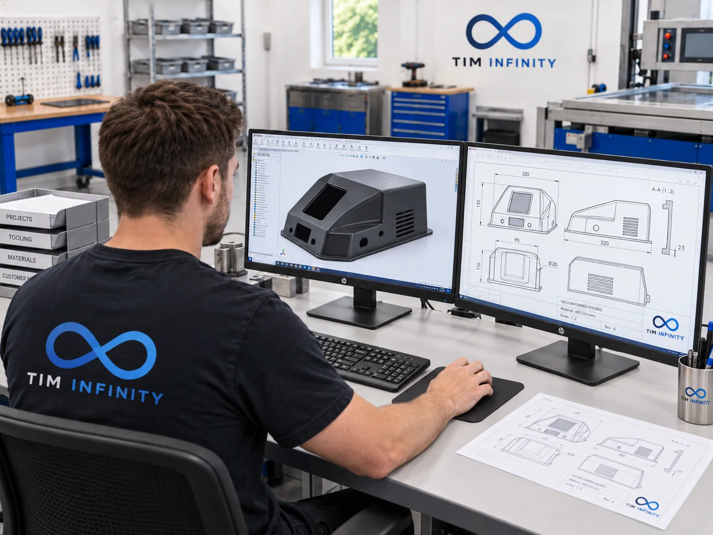
Technical drawing or digital 3D model
Where the product is already structurally defined, a technical drawing or digital 3D model provides the starting point for checking the geometry and developing the corresponding tool.
TIM INFINITY / THERMOFORMING TOOLING
TIM Infinity designs and manufactures tooling and moulds for thermoforming and vacuum forming from a technical drawing, digital 3D model, physical sample of an existing part or a defined requirement for a new product. The tool is developed around the product geometry and dimensions, the material being formed and the requirements of the planned manufacturing process.
ROLE OF THE TOOL
The tool defines the surface geometry to which the heated plastic sheet is formed, so its construction is directly based on the part that needs to be manufactured.
Tooling design is not based only on the final appearance of the product. Radii, draw depth and draw direction, release of the formed part, vacuum-hole layout and subsequent finishing all need to be considered.
For this reason, the tooling and the plastic product are developed as interdependent elements of the same technical solution.
INPUT DATA
Where the product is already structurally defined, a technical drawing or digital 3D model provides the starting point for checking the geometry and developing the corresponding tool.
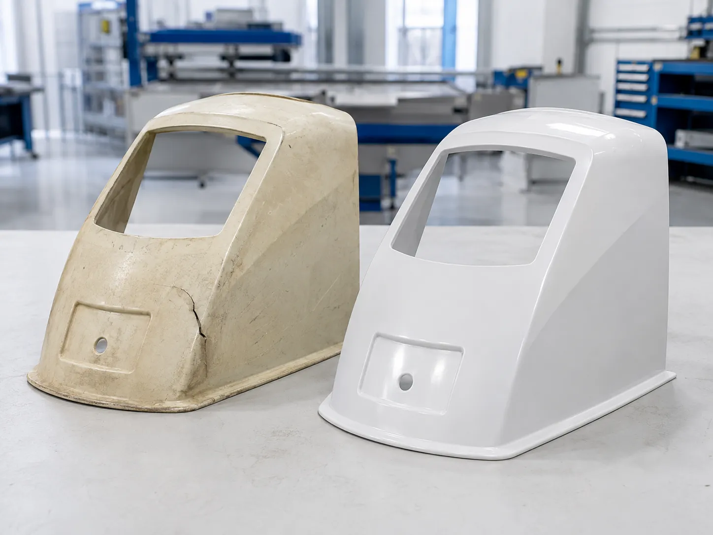
An existing product can provide the starting point where technical documentation is not available or where a tool needs to be developed to reproduce or modify a part.
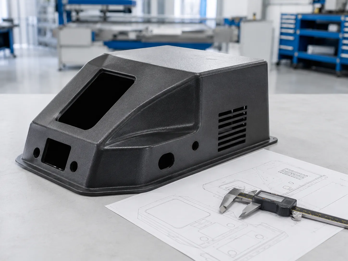
Where the product is not yet structurally defined, its function, basic dimensions, geometry and conditions of use are agreed first. A solution suitable for thermoforming and the corresponding tooling can then be developed.
TOOL DESIGN
Tool geometry must allow the plastic sheet to form correctly and the finished part to be released safely. Draft angles, radii, depth and transitions between surfaces are defined according to the product geometry and the capabilities of the thermoforming process.
The position and distribution of vacuum holes affect how the heated material is drawn onto the tool surface. Their layout is adapted to the part geometry to achieve even and controlled forming.
The tool must allow the formed product to be released reliably after cooling. Draw direction, undercut surfaces and details that may make part removal more difficult are therefore checked during design.
The surface quality of the tool can affect the appearance of the thermoformed product. The required level of finishing is defined according to the material, part application and the requirements for the final surface appearance.
TOOLING MATERIALS
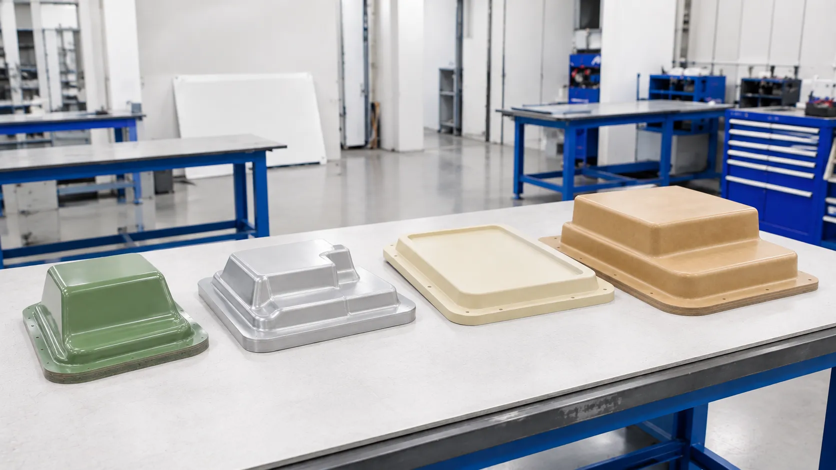
Tooling material is selected according to product geometry, the stage of development, required surface characteristics, expected tool use and planned manufacturing.
Depending on the project, TIM Infinity manufactures tooling from:
wood · MDF · modelling / tooling boards · aluminium · polyester and epoxy systems
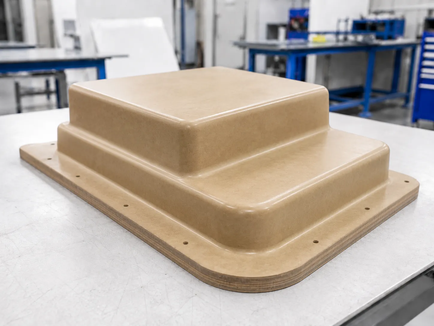
Wood and MDF allow relatively straightforward machining and geometry corrections and can be suitable for certain development, prototype or manufacturing requirements where their properties suit the specific project.
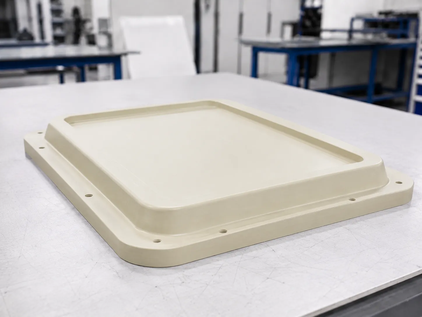
Modelling boards allow accurate machining of defined geometry and are used where a more stable material structure, good machinability and a good tooling surface are required.
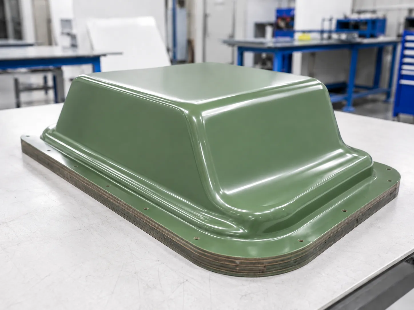
Polyester and epoxy systems can be used for tooling where the manufacturing method suits the product geometry and planned manufacturing.
They can be particularly useful where tool geometry is developed from a previously produced model or master.
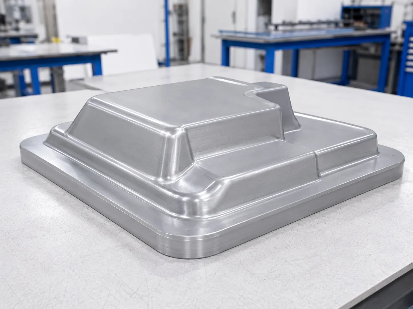
Aluminium is considered where greater tool life and dimensional stability are required, together with improved heat transfer during repeated manufacturing cycles.
Tool material is not selected only according to the desired number of parts. Product dimensions and geometric complexity, required stability, the possibility of corrections and the requirements of the process itself are also considered.
MANUFACTURING PROCESS
01
Product geometry, dimensions, material, required appearance and planned quantity are reviewed to define the basic tooling requirements.
02
Tool geometry is developed from the product. Draft angles, radii, vacuum holes and the details required for correct forming and part release are defined.
03
The tooling material is selected according to product complexity, surface requirements, required tool life and planned manufacturing volume.
04
The tool is manufactured to the defined geometry and its surfaces and functional details are prepared for trial forming.
05
After the tool has been manufactured, a trial forming cycle is carried out to check geometry, forming of critical areas, part release and any need for corrections.
TOOL TYPE
Not every project needs to begin with a tool of the same construction, material and service life. The appropriate solution depends on the product-development stage, required number of parts, surface requirements and whether the objective is to validate a concept or prepare for repeat manufacturing.
Prototype tooling can be appropriate when the goal is to verify product geometry, appearance or function before a final decision is made on the manufacturing solution.
For repeat and series manufacturing, the tooling construction and material are selected to provide the required process stability, surface quality and planned number of cycles.
CONNECTION WITH MANUFACTURING
Thermoforming tooling is not designed independently of the product that needs to be produced. Part geometry, thermoplastic material type and thickness, forming depth, radii, release method and finishing requirements all influence the tool design.
Tooling design and definition of the thermoforming process should therefore be treated as connected stages of product development. A well-matched tool supports more stable forming, easier part inspection and more reliable repetition of the manufacturing process.
Thermoforming & Vacuum FormingINFORMATION FOR ASSESSMENT
A fully completed tooling design is not required for an initial assessment. The most important information is the product to be thermoformed and the requirements the tool needs to support.
Send details for assessmentAllows geometry, dimensions, radii and other design details relevant to tooling development to be checked.
Can be used as the starting point where documentation is not available or where tooling is being developed from an existing product.
If already defined, this information helps assess the forming method and the required tooling construction.
Information about visible surfaces, texture and required final appearance is important for selecting the tooling material and level of finishing.
It is important to know whether the objective is a first-off part, prototype, small production run or repeat manufacturing.
Fit, critical dimensions, openings, areas requiring subsequent processing and other requirements that influence the tool design.
FAQ
SEND AN ENQUIRY
Send a technical drawing, 3D model, photographs, physical sample or the basic information about the product you need to thermoform. Based on the available information, we can assess the starting solution and the next steps for tooling development.
Send an enquiry